Lab 3 LED 3 Colors (RGB)
อุปกรณ์
1.NodeMCU ESP-12E Development Board V2

2.สาย USB-A to Micro-B ตัวผู้ (ควรเป็นสายที่สามารถรับส่งข้อมูลได้)

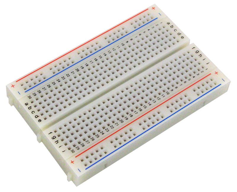
3.Breadboard
4.สาย jumper ตัวผู้

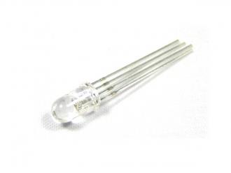
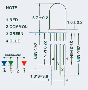
5.หลอด LED
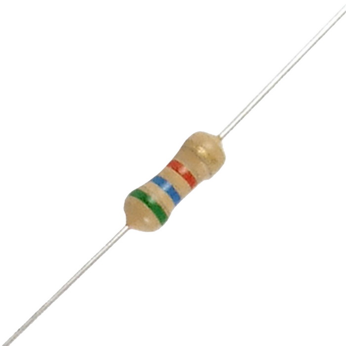
6.ตัวต้านทาน
การต่อวงจร

ขั้นตอนการปฏิบัติ
ขั้นตอนการปฏิบัติ
1.เชื่อมต่อ NodeMCU ESP-12E Development Board V2 เข้ากับคอมพิวเตอร์ของท่านโดยการเสียบสาย USB-A to Micro-B ด้านที่เป็น Micro-B เข้ากับ NodeMCU ESP-12E Development Board V2 และเสียบด้านที่เป็น USB-A เข้ากับ Port USB ของคอมพิวเตอร์
2.เปิดโปรแกรม Arduino IDE ขึ้นมา จากนั้น ท่านจาสามรถพิมพ์หรือคัดลอก source code ข้างล่างไปวางในใน Arduino IDE
#define R_pin D0                // Red    GPIO16
#define G_pin D1                // Green  GPIO5
#define B_pin D2                // Blue   GPIO4
int start_R = 0;                // Initialize red as zero
int start_G = 0;                // Initialize green as zero
int start_B = 0;                // Initialize blue as zero
void setup() {
  pinMode(R_pin, OUTPUT);       // Initialize the R_pin as an output
  pinMode(G_pin, OUTPUT);       // Initialize the G_pin as an output
  pinMode(B_pin, OUTPUT);       // Initialize the G_pin as an output
}
void loop() {
  displayRGB(0, 0, 0);          // Drive RGB LED with 3-bit data (No color)
  delay(2000);
  displayRGB(1, 0, 0);          // Red
  delay(2000);
  displayRGB(1, 1, 0);          // Yellow
  delay(2000);
  displayRGB(0, 1, 0);          // Green
  delay(2000);
  displayRGB(0, 1, 1);          // Cyan
  delay(2000);
  displayRGB(0, 0, 1);          // Blue
  delay(2000);
  displayRGB(1, 0, 1);          // Magenta
  delay(2000);
  displayRGB(1, 1, 1);          // White
  delay(2000);
}
void displayRGB(int R, int G, int B) {
  // Send 3-bit digital data to 3 output pins function
  digitalWrite(R_pin, R);
  digitalWrite(G_pin, G);
  digitalWrite(B_pin, B);
}
หรือ
#define R_pin D0 // Red GPIO16
#define G_pin D1 // Green GPIO5
#define B_pin D2 // Blue GPIO4
int start_R = 255; // Initialize red as 255 (maximum)
int start_G = 0; // Initialize green as zero
int start_B = 0; // Initialize blue as zero
void setup() {
  pinMode(R_pin, OUTPUT); // Initialize the R_pin as an output
  pinMode(G_pin, OUTPUT); // Initialize the G_pin as an output
  pinMode(B_pin, OUTPUT); // Initialize the G_pin as an output;
}

void loop() {
  for (int i = 0; i < 256; i++)               // Set loop
  {
    start_B = 0;                              // Clear BLUE data
    start_G++;                                // Increase GREEN data
    displayRGB(start_R, start_G, start_B);    // Drive LED with PWM
    delay(30);                                // Short delay
  }
  for (int i = 0; i < 256; i++)
  {
    start_R--;                                // Decrease RED data
    displayRGB(start_R, start_G, start_B);    // Drive LED with PWM
    delay(30);                                // Short delay
  }
  for (int i = 0; i < 256; i++)
  {
    start_R = 0;                              // Clear RED data
    start_B++;                                // Increase BLUE data
    displayRGB(start_R, start_G, start_B);    // Drive LED with PWM
    delay(30);                                // Short delay
  }
  for (int i = 0; i < 256; i++)
  {
    start_G--;                                // Decrease GREEN data
    displayRGB(start_R, start_G, start_B);    // Drive LED with PWM
    delay(30);                                // Short delay
  }
  for (int i = 0; i < 256; i++)
  {
    start_G = 0;                              // Clear GREEN data
    start_R++;                                // Increase RED data
    displayRGB(start_R, start_G, start_B);    // Drive LED with PWM
    delay(30);                                // Short delay
  }
  for (int i = 0; i < 256; i++)
  {
    start_B--;                                // Decrease BLUE data
    displayRGB(start_R, start_G, start_B);    // Drive LED with PWM
    delay(30);                                // Short delay
  }
}
void displayRGB(int R, int G, int B)          // Drive LED with PWM by using analogWrite function
{
  analogWrite(B_pin, B);
  analogWrite(G_pin, G);
  analogWrite(R_pin, R);
}
3.จากนั้นให้ท่านทำการ verify และ upload source code ไปยัง NodeMCU ESP-12E Development Board V2
ผลลัพธ์
ท่านจะสังเกตเห็นว่า LED จะเปลี่ยนสีไปตาม source code ที่ท่านได้ upload โดยจะเเรื่มต้นจากไม่มีสี, แดง, เหลือง, เขียว, ฟ้า, น้ำเงิน, ม่วง, และขาว ตามลำดับวนไปเรื่อยๆ ในส่วนของ PWM LED จะค่อยเปลี่ยนสี ไม่ได้เปลี่ยนแบบฉับพลัน


